


Alternative fuels effecting torsional vibrations

07 May 2021
Further details of this study will be presented at the Webinar of the Torsional Vibration Symposium, May 19th at 3 pm (European time), see https://torsional-vibration-symposium.com/
By Dr. Klaus Prenninger, Dr. Lothar Kurtze, Geislinger GmbH
Stefan Eicheldinger, Prof. Georg Wachtmeister, Institute of Internal Combustion Engines, Technical University of Munich
Emission reduction strategies for large bore combustion engines have been a major topic in engine development over the last years. One important factor is the fuel itself. The new technologies applied in the developments to use different fuels have diverse impacts on torsional vibrations.
To study these effects more in detail, test bench setups, like this 4.77-l single-cylinder research gas engine of the Chair of Internal Combustion Engines (LVK) of the Technical University of Munich (TUM), are a valuable option. This engine was developed at TUM based on the cylinder head and piston of an industrial gas engine. To implement combustion processes with high peak combustion pressures of up to 300 bar, the crankshaft, piston rod and bearings have been revised and reinforced. Numerous research tasks concerning engine and emissions performance have been successfully carried out with this engine.
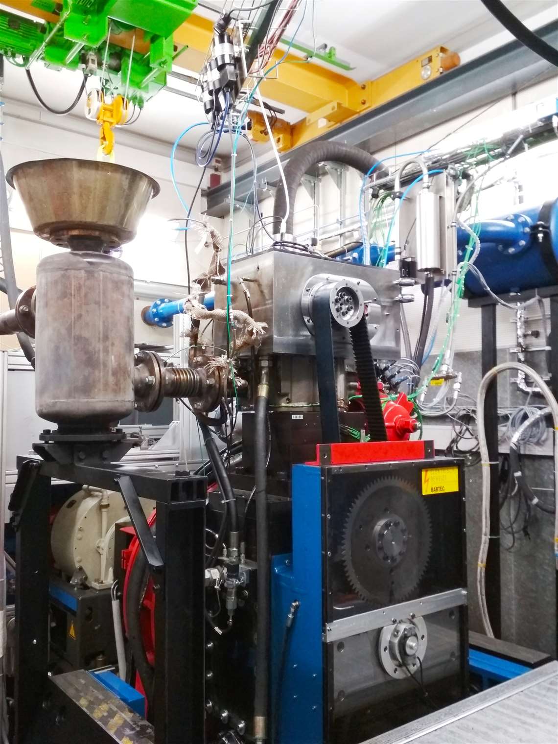 Figure 1: Research gas engine at TUM
Using alternative fuels, the engine vibrations can change considerably. One factor is the difference of the pressure in the cylinder during the combustion process, see the table and pressure curves below.
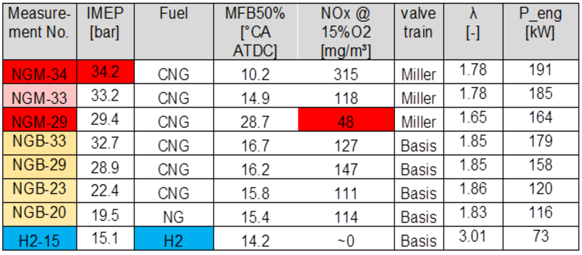 Figure 2: Measurements with different fuels and engine settings
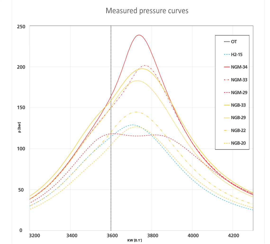 Figure 3: Measured pressure curves with different fuels and engine settings
Different pressure curves of this single cylinder research gas engine have been measured. Different types of Compressed Natural Gas up to an indicated mean effective pressure (IMEP) of 34 bar have been used to study its effect on the Torsional Vibrations (TV). The combustion of hydrogen was also used for these studies. These pressure curves were transferred to engine excitations and applied on a TV model of a regular 16V genset application. The Geislinger Damper (below, left) and Coupling (left of the engine) are marked in red.
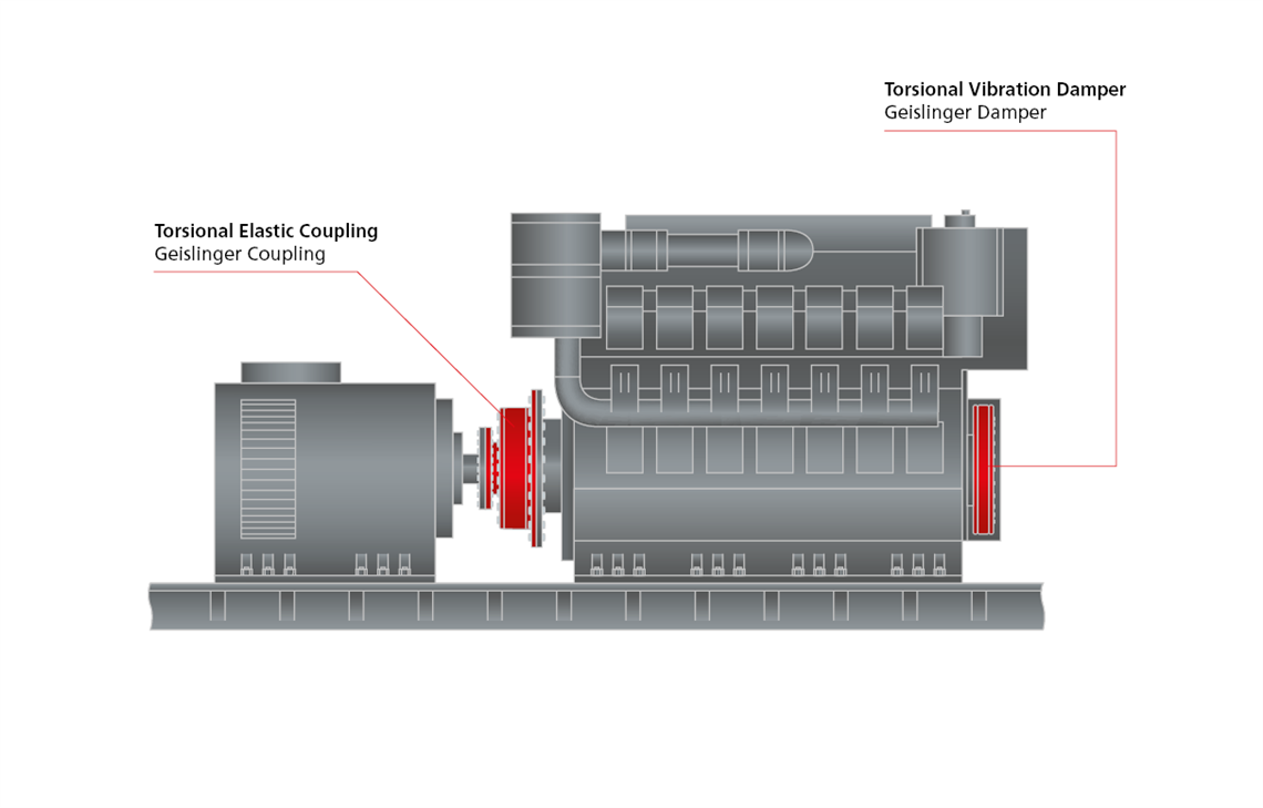 Figure 4: A Geislinger coupling (left) and damper (right) in the powertrain, marked in red
Even hydrogen with a quite low IMEP of 15 bar show, that the TV stress limit of the crankshaft is exceeded without a TV damper. Compared to the diesel engine, a 30% higher TV stress in the crankshaft for hydrogen can be seen, even with a state-of-the-art TV damper. On the other hand, an IMEP of 34 bar show, that even with a special tuned TV Damper the crankshaft is still overloaded. In such a case additional design loops for this application between the engine builder and the damper and coupling supplier are required for further design optimizations. Due to such studies, Geislinger has built up the knowledge to individually optimize the dampers and couplings depending on the engine builders’ concepts. This optimization goes hand in hand with the engine builder in order to achieve highest overall system efficiency and reliability. The image below shows the single components of a tuned spring damper (aka Geislinger Damper), where the steel springs and all other parts can be adapted and built individually to match the design targets and required vibration levels.
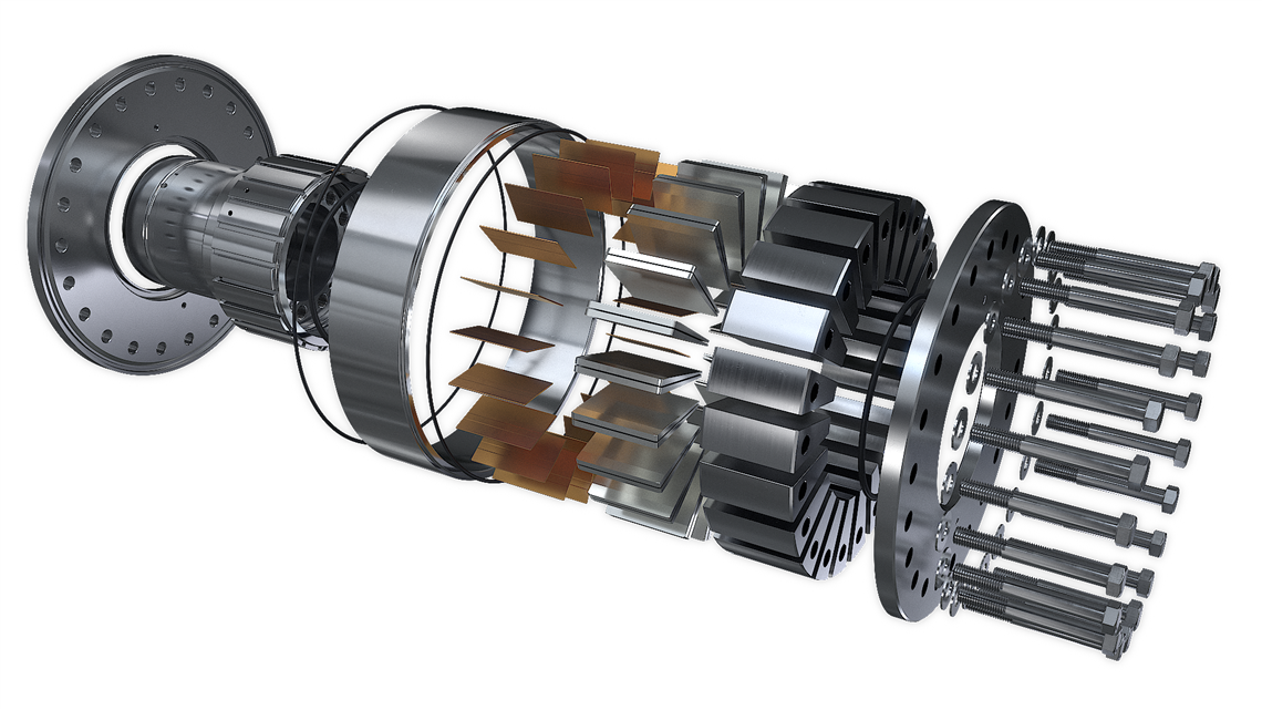 Figure 5: The design of a Geislinger Damper
Not only the torsional vibration levels might increase significantly, but also the structure-borne noise from the engine into the ships’ hull. To minimize the transfer of the structure-borne noise along the powertrain, the Geislinger Silenco Coupling is a powerful option. The coupling is made from carbon and glass fiber combined with elastomer layers. The segments are connected by steel bolts. The figure below shows a picture of such a coupling. The outer sides are the acoustically optimized flanges. They are designed with elastomer layers inside the power flow. Thus, the structure-borne noise will be reduced as the sound pressure wave passes the materials with different impedances and damping factors. In between these acoustic flanges, the membranes of the couplings are located. They permit the necessary misalignment between input- and output shaft. In the middle, the membranes are connected to a lightweight composite shaft. The length can vary depending to the necessary misalignment and the customers’ needs. The combination of highest acoustic performance with minimized weight allows for even more efficient powertrains.
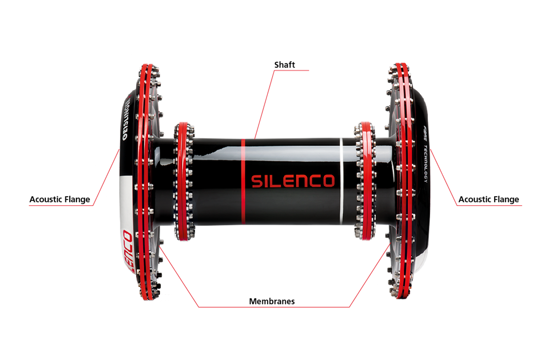 Figure 6: The Geislinger Silenco Coupling
STAY CONNECTED


Receive the information you need when you need it through our world-leading magazines, newsletters and daily briefings.
CONNECT WITH THE TEAM